
The main area of our activities in the field of aviation and space technologies is the provision of research and development services and supporting the development of industry. Theoretical, design and calculation, and laboratory work are the elements that distinguish us on the market among world leaders.
Aviation and space research – scope of services
- experimental and computational research in the field of aerodynamics;
- aviation structures testing;
- landing gears testing;
- advanced drives (power transmissions) (BLI, RDE) testing;
- R&D in the field of air transport systems;
- rocket hybrid engines testing;
- development of technologies for ecological propellants;
- creating dedicated CFD and FEM software;
- flight dynamics analysis of the multi-stage rockets;
- internal ballistics analysis of the rocket engines;
- SORA operational risk analysis.
We are one of the few centers in Poland performing work in the development of new rocket technologies for civilian applications. We specialize in the design and testing of rocket engines and carrier rockets powered by green propellants.
All research work is carried out using professional programming like CATIA and ANSYS FLUENT.
Testing of aeronautical structures
Łukasiewicz Research Network – Institute of Aviation is a leader in the research of aeronautical structures. In our specialized Research Centers and Laboratories we provide a wide range of services to customers in the aviation and industrial sectors, as well as in other sectors related to aviation technology.
Our team of highly skilled engineers carries out the highest quality research of aeronautical structures using modern research equipment. With many years of experience in the aerospace industry, our comprehensive offer of research services meets the highest requirements of our customers.
Testing of aeronautical structures – scope
We use state-of-the-art research equipment to warrant the results’ accuracy and reliability. Our services include:
- Strength testing – we perform static, quasi-static, dynamic and functional tests. We also perform impact tests, crawling tests, and fatigue tests.
- Non-destructive testing – we offer tests using ultrasonic, penetrating, magnetic-powder, and visual methods. Our tests allow for early detection of defects and faults, which enables a quick response and minimizes repair costs.
- Material research – we perform physical and chemical, microstructural, diffraction analyses. We verify compliance with standards.
- Vibroacoustic studies – we carry out acoustic tests and examine vibration and aeroelastic properties, also under operating conditions. Depending on the needs of our customers, we can offer technical solutions that increase the strength of specific elements.
We test aeronautical structures in accordance with the highest standards of safety and quality. Our individual approach to each customer allows us to tailor our services to individual needs.
Strength tests
We offer comprehensive tests in accordance with FAR, EASA, MIL, AP standards for helicopters and aircraft with a takeoff weight of up to 20,000 kg (44,000 lbs). We carry out tests of complete assemblies, as well as their components, in terms of energy consumption, static, dynamic and fatigue strength, dynamic characteristics, functional characteristics and resistance to shock loads.
Strength tests – scope of the tests
- static and quasi-static tests,
- dynamic tests,
- functional tests.
The measured and recorded quantities are:
- time,
- force,
- displacement and deformation,
- pressure,
- temperature,
- speed of rotation,
- acceleration,
- voltage and current.
Strength tests – documentation
Documenting of the conduct of the tests using:
- computer A/C recorders with 12- and 16-bit signal converters (maximum 1M samples/second), with up to 256 configurable input channels – equipment from Keithley Metrabyte, National Instrument, IOtech and Advantech;
- SPIDER 8 mobile system (Hottinger);
- MGC and KWS amplifiers from: Hottinger Baldwin Messtechnik, MPL from Peltron and TD from Czaki, supporting accurate constant-voltage sensors and 4.8 kHz carrier-wave sensors;
- pressure, acceleration, linear displacement, force and strain transducers from: Hottinger, Keithley and Peltron;
- equipment for calibration, electrical measurements, generation of sinusoidal waveforms using equipment from:
- Keithley Metrabyte,
- VIS,
- Mitutoyo;
- measurement and control applications for data collection, control, generation of reports prepared in the laboratory, using TestPoint CEC and LabView software, based on the PC Windows platform;
- real-time flight recorders with sensors dedicated to rotating objects;
- LabView software with vision, RT, FPGA modules;
- Soria high-speed camera system with proprietary software, 180 fps at 2000×2000 resolution;
- NI DIAD for processing large amounts of data and synchronizing with video files.
Vibroacoustic tests
We perform resonance tests of aircraft and other objects, also outside the aviation industry, in order to determine their dynamic properties. Based on the results of resonance tests, we perform numerical analyses in the field of aeroelasticity, allowing us to determine the velocities and flutter forms, in accordance with the requirements of aviation regulations. We perform vibration tests, acoustic tests and measurements of other quantities and parameters characterizing an operation, enabling the diagnosis of the condition of a machine, device, vehicle or aircraft in their operating conditions. We carry out tests commissioned by external Clients, our own research work and work carried out as part of projects conducted at the Institute. The mobility of all elements of the laboratory equipment makes it possible to perform analyses in a place agreed with the Customer.
Vibroacoustic tests – equipment
- multi-channel SCADAS analyzers/recorders:
- SCADAS LAB – 128 measurement channels (V8 inserts),
- SCADAS MOBILE – 64 measurement channels (V8E inserts),
- SCADAS MOBILE – 64 measurement channels (VB8E inserts – strain gauges),
- SCADAS MOBILE – 16 measurement channels (V8 inserts);
- acceleration sensors:
- 1-axis and 3-axis,
- different sizes:
- from 8.6 mm (miniature) to 56 mm (seismic),
- from 0.3 grams to 210 grams;
- different measuring ranges:
- frequencies from 0.5 Hz to 40,000 Hz,
- accelerations from 8·10-6 g to 1000 g;
- a total of over 300 pieces of various types of acceleration sensors;
- modal (impact) hammers:
- PCB 086D50 (weight 5.5 kg, range 22 kN),
- PCB 086D20 (weight 1.1 kg, range 22 kN),
- PCB 086C03 (weight 0.16 kg, range 2.2 kN),
- PCB 086C01 (weight 0.1 kg, range 444 N),
- PCB 086D80 (weight 4.8 g, range 222 N);
- electrodynamic inductors:
- EDSW-200 (2000 N) – 2 pcs,
- PRODERA 20JE20/C (200 N) – 8 pcs,
- PRODERA EX303C (50 N) – 6 pcs,
- TMS 2100E11 (440 N) – 1 pc.,
- LD 100 (8.8 N) – 2 pcs;
- laser vibrometer:
- Polytec PSV 500 3D – non-contact vibration measurement;
- acoustics:
- acoustic camera,
- microphones,
- intensity probe,
- sound and vibration analyzer.
Vibroacoustic tests – software
- resonance tests/vibration tests – LMS Test.Lab:
- MIMO Sweep & Stepped Sine Testing,
- MIMO Normal Modes Testing,
- Impact Testing,
- Operational Modal Analysis;
- Acoustics – LMS Test.Lab:
- HD Acoustic Camera,
- Sound Intensity Testing,
- Sound Intensity Analysis;
- recording signals over time:
- LMS Test.Xpress.
Research of Space Components
In the year 2023 in Warsaw a modern research unit – the Laboratory Center for Rocket and Satellite Propulsion – was put into operation, which complements the research offer of the Łukasiewicz – Institute of Aviation in the field of space technologies. The infrastructure is intended for both qualification and industrial research and development work, including:
- development and qualification of ecological rocket and satellite green propulsion systems,
- development of novel propellants, with emphasis on ecological and hypergolic fuels,
- development of systems for satellite deorbitation,
- development of pyrotechnic components and electronic components systems.
Research of Space Components – Scope
Design and tests of space technologies are carried out in a number of laboratories, including:
Space propulsion research laboratories:
- Rocket propulsion test facility – tests in atmospheric conditions, units up to 5 kN of thrust,
- Satellite propulsion test facility – tests in atmospheric conditions, units up to 20 N of thrust,
- Space propulsion test facility – tests in conditions of continuous vacuum, units up to 500 N of thrust,
- Rotating detonation engine test facility (RDE) – for gaseous and liquid fuels.
Chemical laboratories:
- Catalyst Laboratory
- Solid Propellant Laboratory
- Synthesis Laboratory
- Liquid Fuels Laboratory
- Thermal Test Laboratory
- Analytical Laboratory
Rocket and space subsystems test laboratories:
- Actuation and Control Systems Laboratory
- Space Avionics Laboratory
- Flow Components and Valves Laboratory
- Injector Test Station
Rocket propulsion test facility - tests in atmospheric conditions up to 5 kN
The Atmospheric Rocket Engine Test Facility was created in response to the rapidly growing space and defense sector. It is a modern, high‑performance facility designed for engine testing under sea-level conditions, representing the environment most characteristic of the rocket’s initial ascent phase. This allows for precise evaluation of ignition systems, combustion characteristics, flow dynamics, and the full operational profile of the propulsion system under realistic loads with extensive instrumentation.
By combining advanced infrastructure, state‑of‑the‑art measurement equipment, and an experienced research team, the atmospheric rocket engine test facility is one of the most capable and mature facilities of its kind in the country and Europe. It facilitates development, certification, and qualification testing for a wide range of engines and propulsion components, providing accurate and essential data for rocket engine design, development, and optimization.
Engines tested in the facility can be used for:
- primary and auxiliary rocket propulsion,
- orbital correction,
- orientation control,
- deep space missions,
- planetary landing systems.
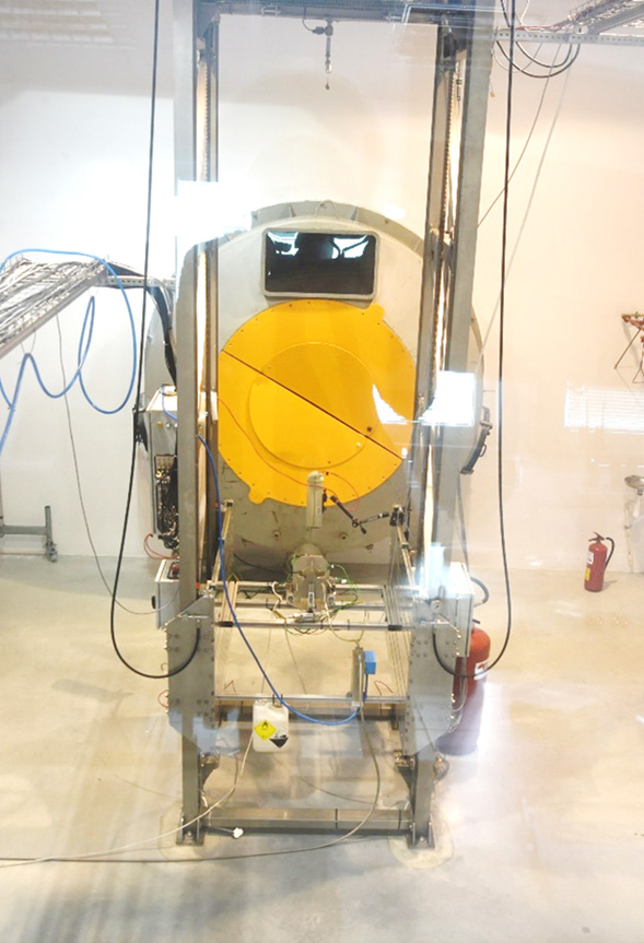
Test stand of The Atmospheric Rocket Engine Test Facility
The scope of testing
- mono‑ and bipropellant engines,
- engines operating on green propellants
- liquid: hydrogen peroxide, alcohols, kerosene, TMPDA, pyridine;
- hybrid: hydrogen peroxide with polymer fuels,
- engines up to 5 kN thrust,
- vertical and horizontal testing configurations,
- component testing (valves, pyrotechnics),
- measurement of key physical quantities such as pressure, temperature, force, flow rate, and vibrations.
Test facility
- Dedicated building housing the test cell, control room, and workshop, enabling year‑round testing regardless of weather conditions. It features acoustic insulation, a 50‑meter exhaust silencer, reinforced walls, and advanced safety systems to protect personnel and the surrounding area.
- The test stand is a modular frame equipped with vertically movable plates for flexible installation in both vertical and horizontal configurations. Materials were selected for compatibility with hydrogen peroxide and resistance to fuels and combustion products. Standard mechanical interfaces ensure fast integration. Usable mounting space is 2.10 m (height), 1 m (width), and 3 m (depth).
- Propellant supply systems include three oxidizer‑fuel installations with capacities of 52, 20, and 8 dm³. They provide pressures up to 40 barA (60 barA for the 8‑dm³ system) and flow rates up to 2 kg/s. Nitrogen pressurization is handled by automated, remotely controlled pressure regulators. A direct connection to a liquid nitrogen storage facility ensures almost unlimited availability of nitrogen.
- The exhaust deflector enables vertical engine testing by cooling exhaust gases with an automatic water‑injection system before redirecting them horizontally into the silencer.
- A regulated water‑cooling system prevents overheating of test articles. At maximum flow (4 kg/s), the test duration is approximately 250 seconds, with longer tests achievable under lower cooling demand.
- The integration workshop supports the preparation of test articles and infrastructure. It includes standard tools, PPE for handling hydrogen peroxide and fuels, quality‑control devices (borescopes, microscopes, metrology tools), helium leak‑testing equipment, mechanical and hydraulic fittings, and a complete electronics workstation (soldering station with extraction, oscilloscope, power supplies, inspection microscope).
- The control and measurement system is based on a real‑time PXI platform from National Instruments, developed in‑house. Proprietary software allows rapid customization and smooth integration of non‑standard client equipment.
Measurement capabilities
- Measurement capabilities include core physical measurements (pressure, temperature, mass flow, force, vibrations) using nearly 200 independent channels with sampling rates up to 2 MS/s.
- Control capabilities include up to 100 digital outputs (5 VDC, 24 VDC, 28 VDC, 230 VAC via relays), analog outputs between –10 and 10 VDC at 16‑bit resolution, and control line update frequencies up to 1 kHz.
- The vision system supports Full HD cameras up to 60 Hz, thermal cameras, and high‑speed cameras reaching up to 1 MHz for fast transient events.
- Instrumentation available to clients includes devices from Kistler, Keller, ZEPWN, HBM, PCB, Czaki, and others.
Safety
- Test stands are designed to minimize risk and environmental impact. Materials are selected for compatibility with commonly used propellants.
- The real‑time software enables definition and continuous monitoring of operational limits. In case of anomalies, the system can respond autonomously within 10 ms, executing predefined safety procedures faster than human operators.
- A remotely activated fire‑suppression system supports emergency response. For situations beyond its scope, the control room includes an alert system for specialized emergency services.
Engineering support
As part of project execution, in addition to conducting tests and preparing reports, advisory and engineering support services are also provided.
A technical support team operates within the test facility, ensuring comprehensive handling of test articles and the infrastructure used during integration, assembly, and testing processes. The team’s competencies include technical, technological, and quality support at all stages of project execution—from the preparation of components and test stands, through system integration, to operation and supervision during test campaigns.
To support ongoing work, the team provides infrastructure that includes a component warehouse with a full identification and traceability system for all parts used in the construction of test articles and experimental setups. Projects also have access to an integration area equipped with dedicated assembly stations and workshop facilities that enable a wide range of assembly tasks in accordance with technical documentation. Additionally, a controlled‑environment workspace (ISO 7 clean room) is available for tasks requiring elevated cleanliness standards.
The technical facilities are complemented by a mechanical workshop that enables the fabrication of simple parts, routine modifications, and repairs using machining, fitting, and welding processes. An integral part of the infrastructure is also the internal quality control department, which performs dimensional inspection, 3D scanning, and supports quality assurance in projects, as well as pressure and vacuum helium leak tests using a helium detector.
The team consists of experienced specialists who provide technical and organizational support at every stage of preparation, integration, and test execution, with full adherence to high standards of quality, occupational safety, and best practices in workplace organization, including the 5S methodology.
Spacecraft propulsion test facility of continuous vacuum conditions
Europe’s newest rocket engine test facility for vacuum conditions, commissioned in 2023, enables the testing of engines and components in an environment that replicates the conditions found in space. Precise measurements of key parameters, such as thrust, pressure and operating time, form the basis for optimising, assessing the durability and reliability of rocket engines (satellites), which has a direct impact on the safety and success of space missions.
The infrastructure has been designed with a focus on the highest safety standards. Control, automation and multi-level monitoring systems minimise the risk of failure, ensuring stable test conditions even during long-term trials. In addition, selected components of the installation meet the requirements of the ATEX directive, enabling safe operation in environments potentially exposed to flammable or explosive materials. Compliance with explosion-proof standards increases the system’s resilience to adverse events and enhances the level of protection for personnel and equipment.
The test centre operates a technical support team that provides comprehensive support for test facilities and the infrastructure used in the integration, assembly and testing processes. The team’s remit covers technical, technological and quality support at all stages of project implementation – from the preparation of components and test benches, through system integration, to the management and supervision of the testing process.
To support the work being carried out, the team provides infrastructure facilities including a component warehouse with a comprehensive identification and traceability system for parts used in the construction of test facilities and test benches. Projects also have access to an integration area equipped with dedicated assembly stations and workshop facilities enabling a wide range of assembly work to be carried out in accordance with technical documentation. Additionally, a work area with an elevated cleanliness standard (ISO 7 clean room) is available for work requiring controlled environmental conditions.
The technical base is complemented by a mechanical workshop capable of producing simple components and performing on‑demand modifications and repairs, including machining, metalworking, and welding. An internal quality control department forms an integral part of the infrastructure, providing dimensional inspections, 3D scanning, quality assurance support, and both pressure and vacuum leak tests using helium detectors.
The team consists of experienced specialists delivering technical and organisational support at every stage of preparation, system integration, and test execution. All work is carried out in accordance with high standards of quality, safety, and best practices, including the 5S workplace methodology.
Space Propulsion Test Facility – Scope of Testing
- Qualification testing of space propulsion systems with thrust ranging from 0.25 to 500 N, using non‑toxic propellants
- Qualification of complete propulsion systems up to 500 N
- Development testing at higher technology readiness levels (TRL 6–8)
- Endurance testing for up to 2 hours of continuous operation (for 500 N engines)
Space Propulsion Test Facility – Equipment
We operate a test stand in vertical vacuum chamber, serving as the core of the test infrastructure. The facility includes:
Vacuum Chamber
- Volume: 5 m³
- Equipped with a cooled test stand featuring an auto‑calibrating force measurement system
- Incorporates numerous proprietary technological solutions enabling precise verification of all propulsion or full system parameters (including fuel feed systems)
Diffuser
- Pressure recovery ratio: 1:15 – 1:45
- Cooled by an external water‑spray system allowing for continuous maintenance of low‑pressure conditions and performance verification in a vacuum environment
Cooling System
- Gas cooler: 800 kW, inlet temperature up to 2250°C, outlet temperature below 50°C
- Water‑based cooling loop: 1,500 kW, closed‑circuit, up to 2200 l/min, 5 bar(g)
Vacuum System
- Pumping speed up to 30,000 m³/h at 30 mbar
- Ultimate vacuum below 2 mbar
- ATEX‑certified components and compatibility with high concentrations of pure oxygen
- Fully automated control and safety systems
Control System
- Proprietary system for test control, measurement, and safety
- Central control system integrated with all subsystems
- Acquisition rate up to 2 MS/s/channel
- 3 high‑speed CCTV cameras
- Advanced emergency shutdown systems
- 150 sensors measuring temperatures, pressures, flow rates, liquid levels, vibrations, and forces
- 2 thermal imaging cameras
- Shared time‑synchronisation clock for cameras and measurement systems
Oxidizer Supply System
- Compatible with >98% hydrogen peroxide
- Total oxidizer capacity: 800 L
- Operating pressure up to 40 bar(g)
- Advanced two‑stage safety system
Fuel Supply System
- Compatible with various types of fuels
- Total fuel capacity: 400 L
- Operating pressure up to 40 bar(g)
- Advanced two‑stage safety system
Space Propulsion Test Facility – Research Capabilities
- Performance verification of space propulsion systems in realistic (vacuum) operating conditions
- Efficiency and endurance testing
- Qualification of propulsion components and complete propulsion systems
Rotating detonation engine test facility (RDE)
Rotating Detonation Engine Test Facility
The detonative propulsion test facility is equipped with stations dedicated to investigating Rotating Detonation Engines (RDE), an innovative technology that significantly enhances combustion efficiency and has recently attracted strong interest from research centers worldwide. The available test setups enable controlled reproduction of flight conditions for air‑breathing RDE systems and allow comprehensive measurement of key operating parameters. This supports the acquisition of propulsion characteristics and the verification of performance for next‑generation applications, including:
- orbital operations and satellite propulsion,
- defense systems such as missiles and rockets,
- hypersonic flight,
- suborbital missions,
- lunar landers.
Rotating Detonation – research Scope
- experimental investigations of airbreathing RDEs generating up to 5 kN of thrust,
- experimental studies of rocket‑class RDEs in the 10–500 N thrust range,
- measurements of fundamental detonation parameters,
- visual diagnostics of RDE injector systems,
- heat‑transfer studies, including the development of cooling solutions.
Rotating Detonation – Facility Equipment
The test facility is housed in a dedicated building enabling year‑round operations, independent of weather conditions. Its key components include:
Hot‑Air Supply System
- Maximum temperature: up to 180°C
- Mass flow: up to 18 kg/s (tests up to 1.5 s)
- Multi‑stage control enabling significantly longer test durations at reduced mass flows
- Capability to reproduce flight conditions corresponding to Mach 2–3.2 at various altitudes
Propellant Supply Systems
- Supporting the delivery of multiple propellants:
- aviation kerosene (liquid),
- nitrous oxide (liquid),
- propane (liquid),
- ethane (liquid),
- hydrogen (gaseous),
- oxygen (gaseous),
- methane (gaseous).
- Test Stand – equipped with modular frames adapted for air‑breathing RDEs up to 5 kN and rocket propulsion systems, enabling safe and efficient integration of test objects using standard mechanical interfaces and providing thrust measurements. The stand also includes a dedicated exhaust stack for removal of engine combustion products.
- Vision System – enabling test observation and detailed analysis of the high‑frequency, self‑sustaining detonation process within the combustion chamber, including a high-speed camera and a thermal camera,
- Integration workshop – enabling test objects’ integration at the test facility. It is equipped with essential tools, safety equipment, devices for quality and leak inspection using a helium detector, and a set of hydraulic and mechanical standard components. It also includes an electronics station with a wide range of equipment for integrating and diagnosing electrical and electronic systems,
- Technical Support Team – a specialized team provides full support throughout all project stages—from component preparation, system integration, and assembly to test execution and supervision. The infrastructure includes:
- a component storage area with complete part identification and traceability,
- integration space with dedicated assembly stations and workshop facilities,
- an ISO 7 clean room for tasks requiring controlled environmental conditions.
Rotating Detonation – Measurement Capabilities
The LabView‑based measurement system incorporates sensors and instrumentation for assessing detonation stability, including:
- KISTLER 603CAB piezoelectric pressure sensors (1 MHz sampling, 0–1000 bar),
- combustion chamber average‑pressure sensors and Pitot tubes,
- multi‑variable probes from certified suppliers,
- thermocouples (Type K, Type B),
- thermal cameras,
- Coriolis flow meters (20 g/s – 2200 g/s),
- Venturi nozzles compliant with PN‑EN ISO 5167‑3,
- propellant heating system (3 kW total power),
- solenoid valves, pressure gauges,
- National Instruments data‑acquisition cards,
- pressure sensor calibrator.
Rotating Detonation – Safety
All tests are conducted in specially adapted rooms that fully separate personnel from the active test stand while allowing continuous control of the experiment. Observation is ensured through armored windows and high‑speed video footage.
The propellant supply installations and air‑handling systems are equipped with an automated monitoring and control unit that reacts to parameter exceedances by safely aborting the test and shutting off supplies. Personnel can also manually initiate safety procedures to place all systems in a secure state.
The test stands feature comprehensive fire and explosion protection systems certified for ATEX, as well as ventilation systems adapted to the propellants used during experiments.
Chemical laboratories
Expanded in 2023, the Chemical Research Laboratory for space applications enables a global-scale investigation of physico-chemical properties and chemical compatibility of propellant materials.
Łukasiewicz – Institute of Aviation is a leading research and development unit in Poland and worldwide in the field of ecological rocket propulsion. Its primary areas of interest and specialization lie in environmentally friendly liquid and hybrid propulsion systems based on over 98% hydrogen peroxide, as well as innovative hypergolic fuels.
The in-house capabilities of production of hydrogen peroxide with concentrations exceeding 98% are based on a patented method, providing independence in preparations for testing engines and other components utilizing HTP.
The chemical laboratory – tasks
- Research on fuels for new liquid, hybrid, and gel propulsion systems.
- Research on fuels hypergolic with hydrogen peroxide (production, long-term storage, passivation, and compatibility studies).
- Research on chemical durability of fuels containing catalytic and/or energetic additives.
- Investigation of physicochemical parameters useful for propulsion applications.
- Development of advanced low-smoke solid rocket propellant materials.
- Research on high-performance environmentally friendly fuels and oxidizers of a new generation.
- Development of catalysts for single-component propellant applications.
- Research on the chemical compatibility of different structural materials with working fluids.
- Development of fuel compositions that spontaneously react with hydrogen peroxide (hypergolic).
The chemical laboratory – equipment
- Nicolet iS50 FT-IR spectrometer with built-in ATR.
- Vhx 7000 digital microscope.
- Laboratory muffle furnace type FCF 22 SHM.
- Vibratory sieve shaker AS Control.
- Planetary ball mill PM 100.
- Stand for casting solid rocket propellant materials.
Prototypes of propellant materials obtained through casting process and after thermal conditioning must undergo testing to meet specified parameters, including ballistic, mechanical, thermochemical properties, and safety requirements. Only with a ready and properly characterized propellant material can full thruster tests be conducted, which are performed on site on vacuum or atmospheric test stands. Consolidating the research facilities in one place enables comprehensive research and development of solid propellant materials while increasing their safety.
Rocket and space subsystems testing laboratory
The development of rocket and satellite engine components using low-toxicity liquid, solid, gaseous, and gel propellant materials is a natural extension of the Institute’s offerings. Alongside the development of rocket engine families, work is planned on other components of propulsion systems, including propellant tanks, valves, filters, pipelines, structures, interfaces, inert gas pressurization subsystems, and control systems. In addition to our own R&D work, we offer testing, design services, and engineering consulting for external clients and within project consortia.
The design and testing of space subsystems take place in:
- Actuation and Control Systems Laboratory
- Space Avionics Laboratory
- Flow Components and Valves Laboratory
- Injector Test Station
- Cleanrooms of ISO 7 and ISO 8 classes.
The electromagnetic valves laboratory
Allows for comprehensive testing of space flow components during static and flow tests. The laboratory is equipped with:
- Helium detector for precise leakage measurements,
- Flow station where the test object performance can be evaluated under operating flow conditions.
Equipped with two hydraulic lines, the facility allows for simultaneous testing of a pair of single-flow and single dual-flow valves, where, in the latter case, fuel and oxidizer flows are controlled by a common actuator.
Rocket and space subsystems testing laboratory – tasks
The laboratory allows for:
- flow tests with flow rates ranging from 0.2 to 50 g/s (for water) and pressures up to 40 bar
- evaluation of internal and external leakage
- evaluation of back-pressure relief characteristics
- determination of valve response time (opening/closing)
- determination of pressure drop characteristics
- burst pressure tests
- valve cleanliness assessment
- water hammer resistance evaluation
- life assessment through high-cycle testing in operating flow conditions
- determination of electrical parameters such as power consumption, insulation resistance, coil resistance, electrical bonding, pull-in/drop-out voltages etc.
Landing gears testing
We are the leading center for designing and testing aircraft landing gear in Poland. A significant part of the landing gears of aircraft and helicopters manufactured in Polish factories has been designed and tested in our laboratory, which offers a set of comprehensive engineering services, such as design, analysis, testing and supervision over the execution of prototypes. We run, among others, tests of the landing gears, brakes and other structures in the scope of:
- energy intensity,
- static strength,
- dynamic and fatigue,
- dynamic characteristics,
- functional,
- resistance to shock loads in accordance with FAR, EASA, MIL, AP regulations.
We have accreditation of the Polish Center for Accreditation with the number AB-131.
Among the goals we set for ourselves is the development of technology, proposing new construction and technological solutions, their verification with the use of testing methods, construction of test beds and supervision over the implementation of prototypes of technology demonstrators.
Landing gears testing – research scope (in accordance with the scope of accreditation)
- force: 0.1 to 400 kN;
- displacement: 0.05 to 2400 mm;
- relative strains: 10 to 15000 μm/m;
- speed of rotation: 10 to 20000 rpm;
- acceleration: 0 to 200 m/s²;
- pressure: 0 to 60 MPa;
- temperature: -40 °C to +1084 °C.
Measurement methods:
- electrical measurements of physical quantities;
- thermal imaging measurements with the FLIR SC645 camera (out of accreditation);
- measurements with the fast Phantom VEO 410L camera (out of accreditation).
Landing gears testing – scope
Landing gears testing includes, among others:
- aircraft landing gears,
- brakes,
- bearings,
- frictional materials,
- shock absorbers,
- silencers,
- energy intensity,
- static and dynamic strength,
- fatigue,
- dynamic and functional characteristics,
- shock load resistance.
3 T hammer drop stand with treadmill
The hammer is intended for testing shock absorption of aircraft landing gears in conditions similar to those of landing and taxiing, testing “shimmy” vibrations of landing gears, as well as testing brakes, wheels and tires. The stand allows to apply dynamic loads in the form of driving over an obstacle.
3 T hammer drop stand with treadmill – stand specification
- maximum weight of the object with mounting elements: 3 T (expandable to 6.5 T for wheel tests);
- maximum vertical force when dropping: 118 kN;
- maximum rotational speed of the treadmill: 800 rpm;
- maximum perimeter speed of the treadmill: 58.6 m/s;
- treadmill diameter/width: 1400 mm / 530 mm;
- moments of inertia of the treadmill (adjustable):
- I1 = 294 kgm²,
- I2 = 550 kgm²,
- I3 = 588 kgm²,
- I4 = 843 kgm².
3 T hammer drop stand with treadmill – testing characteristics
- dynamic tests (drops),
- shimmy tests,
- approaching an obstacle,
- brake tests,
- wheels rolling.
10 T hammer drop stand
The 10 T hammer is designed to test landing gear shock absorption in conditions similar to those of landing. It is also possible to perform impact tests, for example, on dampers or shock absorbers, as well as tests to determine the energy absorption capacity (crash).
10 T hammer drop stand – stand specification
- maximum weight of the object with mounting elements: 10 T;
- maximum forces when dropping:
- vertical force 392 kN,
- horizontal force 196 kN,
- lateral force 157 kN;
- maximum rebound pressure (unloading): 3 MPa;
- maximum acceleration speed of the wheel: 111 m/s;
- maximum speed of descent: up to 8 m/s – depending on the height of the tested object.
10 T hammer drop stand – testing characteristics
- dynamic tests (drops),
- static tests of the wheels,
- functional tests.
Universal stand for static tests
The stand is intended for static, strength and functional tests of structural elements and entire assemblies. The modularity of the technological equipment used allows the stand to be used as a universal mounting platform.
Universal stand for static tests – stand specification
- Platform dimensions: 6.6 × 2.4 m;
- maximum compressive exciting forces: 20 T – 5 lines;
- maximum compressive tensile forces: 20 T – 5 lines.
Universal test stand for static tests – testing characteristics
- static tests,
- functional tests,
- modular testing and mounting platform providing flexibility of the tests.
40/20 T press
The press is designed to test chassis and their assemblies, i.e. wheels and shock absorbers, in static and slow-change tests. It makes it possible to determine force-displacement characteristics in biaxial loading conditions. The way the objects are built on the stand makes it possible to perform this type of testing also on other, non-aerial objects.
40/20 T press – stand specifications
- maximum vertical force: 392 kN,
- maximum horizontal force: 196 kN,
- vertical displacement: 400 mm,
- maximum vertical speed: 300 mm/min,
- maximum horizontal speed: 300 mm/min,
- table dimensions: 800 × 760 mm,
- distance between table and press slide: 190 to 2000 mm,
- operation in force maintenance mode, displacement mode (continuous or stepwise),
- ability to record displacement and forces (and up to 8 external analog signals).
40/20 T press – testing characteristics
- static tests,
- force-displacement characteristics,
- characteristics of:
- shock absorbers,
- silencers,
- materials,
- static tests of the wheels.
IL-68 stand for testing frictional materials
Modeling the physical phenomena that occur in the brakes when the machine (vehicle, aircraft) is braked, and in particular for modeling the phenomenon of the so-called thermal impact. The braking cycle to zero speed lasts only 10–15 s. During this time, such a large amount of heat is released on the working surface of the brake that a thermal impact is created, directed deep into the elements of the friction pair.
The IL-68 test bed makes it possible to reproduce the phenomena occurring on the friction surface of the tested samples, and at the same time to obtain and measure a number of parameters characterizing the working conditions of the brake and the cooperation of friction pairs. Our offer also includes tests of heat resistance of materials for brake blocks and other friction pairs.
IL-68 stand for testing frictional materials – stand specification
- maximum rotational speed of the drive shaft: 9000 rpm;
- moment of inertia: (adjustable) 0.154 to 1.54 kgm² (in steps of 0.098 kgm²);
- maximum pressure force on the surface of the samples: 5.88 kN.
IL-68 stand for testing frictional materials – testing characteristics
- wear of friction materials;
- friction pair parameters:
- braking torque,
- braking force,
- temperature;
- heat resistance of friction materials.
Analyzes
Basic scope of the analyses we offer:
- static and dynamic loads on aircraft landing gear components and other structures;
- “shimmy type vibration analyses”;
- stiffness-strength analyses, susceptibility of components or entire aircraft landing gear and other structures (including composite);
- optimization and integration of components of aircraft landing gear and other structures, braking system, shock absorbers;
- phenomena accompanying the braking process (dynamics, thermal phenomena, vibrations);
- evaluation of durability of elements of aircraft landing gear and other structures by analytical and experimental methods;
- numerical analyses of energy-consumption of the materials;
- design and analysis of energy-intensive envelope structures (lattice structures) made by incremental methods (3D printing);
- numerical simulations of landing gear drop tests.
We perform analyses using the following packages:
- MSC NASTRAN/PATRAN,
- FEMAP/NASTRAN,
- HYPER WORKS,
- dynamic analysis using LS-DYNA.
Engineering services
The scope of our services:
- wheeled and skid types aircraft landing gear;
- “shimmy” and anti-resonant vibration dampers – single- and double-acting;
- landing gear dampers, actuators and locks;
- test beds;
- ABS anti-skid systems for aircraft landing gear applications;
- wheels and high-energy brakes;
- landing gears for unmanned aerial vehicles (UAV);
- technology demonstrators;
- electric brakes for manned and unmanned aerial vehicles (UAVs);
- assessment of the design process and its compliance with aviation standards;
- designing carried out in the CAD 3D SOLID EDGE environment (compatible with NX and CATIA systems);
- assessment of the state of knowledge in the field of technological solutions of aerial landing gears;
- other solutions depending on the Customer’s needs.
Static and quasi-static test
Static strength tests make it possible to determine the behavior of structural elements or the structures themselves. The test objects are subjected to a uniformly increasing load to a specific value, reaching the assumed deformation or destruction. The recorded changes of force, moment and displacement in time, together with the geometrical dimensions of the tested objects, allow determination of the values of stresses and deformations.
Static strength tests – testing capabilities
We perform static and quasi-static strength tests of complete structures and their elements, including axisymmetric objects (simultaneous stretching and torsion), as well as tests of structure stiffness.
We perform structural tests according to individual Customer orders, including preparation of the project and construction of the test stand.
Static and quasi-static strength tests – equipment:
Schenck-Pegasus testing machine
- axial force: up to 1350 kN;
- twisting moment: up to 452 kNm;
- sample length: up to 3.6 m;
- sample diameter: up to 1200 mm;
- twist angle: ±15°;
- axial displacement: ±50 mm;
- frequency: up to 1 Hz;
- sample maximum temperature: 980 °C.
Dynamic tests
The behavior of structural elements is determined not only in static tests, but also as a result of dynamic tests. This type of strength test, which is one of the basic methods of evaluating the properties of structures and their elements, enables the determination of dynamic mechanical properties. Dynamic tests play an important role in the case of objects intended for operation under dynamic load conditions.
Dynamic tests – testing capabilities
We perform dynamic strength tests of complete structures and their elements. We perform structural tests according to individual Customer orders, including the preparation of the project and the construction of a test stand.
Dynamic tests – equipment:
3 T Hammer Drop Test Stand with Treadmill
The hammer is intended for testing shock absorption of aircraft landing gears in conditions similar to those of landing and taxiing, testing “shimmy” vibrations of landing gears, as well as testing brakes, wheels and tires. The stand allows application of dynamic loads in the form of driving over an obstacle.
Test stand specification:
- maximum weight of the object with mounting elements: 3 T (expandable to 6.5 T for wheel tests);
- maximum vertical force when dropping: 118 kN;
- maximum rotational speed of the treadmill: 800 rpm;
- maximum perimeter speed of the treadmill: 58.6 m/s;
- treadmill diameter/width: 1400 mm / 530 mm;
- moments of inertia of the treadmill (adjustable):
- I1 = 294 kgm²,
- I2 = 550 kgm²,
- I3 = 588 kgm²,
- I4 = 843 kgm².
Testing characteristics:
- dynamic tests (drops),
- shimmy tests,
- approaching an obstacle,
- brake tests,
- wheels rolling.
10 T Hammer Drop Test Stand
The 10 T hammer is designed to test landing gear shock absorption in conditions similar to those of landing. It is also possible to perform impact tests, for example, on dampers or shock absorbers, as well as tests to determine the energy absorption capacity (crash).
Test stand specification:
- maximum weight of the object with mounting elements: 10 T;
- maximum forces when dropping:
- vertical force: 392 kN,
- horizontal force: 196 kN,
- lateral force: 157 kN;
- maximum rebound pressure (unloading): 3 MPa;
- maximum acceleration speed of the wheel: 111 m/s;
- maximum speed of descent: up to 8 m/s – depending on the height of the tested object.
Testing characteristics:
- dynamic tests (drops),
- static tests of the wheels,
- functional tests.
Functional tests
Site in progress
Tests in operating conditions
We perform operational vibration measurements of machines, devices, and vehicles during their operation. The data acquisition system used for this purpose enables vibration measurement at multiple points (up to 256 channels) using appropriate sensors, as well as measurement and recording of other physical quantities necessary for monitoring operation and assessing the condition of the tested equipment.
Available inputs include voltage sensors (+/- 10 V), ICP/IEPE, and strain gauge bridges (1/4-, 1/2-, and full bridge). The high sampling frequency of the measurement system (up to 204 kHz) allows for the study of rapidly changing phenomena, such as collisions with the tested structure of objects launched from a pneumatic gun, or transient states such as device start-up or braking.
Strain gauge tests
This is one of the most commonly used methods for measuring deformations on a given surface. They enable the determination of stresses in order to assess the strength of the structure or its elements. The tests are also used to determine the forces and moments of forces in operating conditions. The quality of the sensors and measurement systems used plays an important role.
Strain gauge tests – testing capabilities
We offer the preparation of strain gauge measuring points in various configurations, including the installation of standard foil strain gauges, including gluing and soldering. We perform strain gauge measurements in flight and process the obtained results. To collect and record measurement data, we use computerized measurement and recording systems with the possibility of connecting force and displacement transducers, resistance strain gauges, and thermocouples. The maximum number of measurement channels is 250.
Strain gauge tests – equipment
- CompactRIO real-time controller and NI 9237 modules;
- CompactRIO real-time controller:
- two Ethernet ports for network and file support via the user interface;
- external USB memory port;
- RS232 serial port for connecting peripheral devices – 9 to 35 VDC;
- operating range from -20 °C to 55 °C.
- NI 9237 modules:
- 4 channels, ±25 mV/V, 24-bit bridge module;
- 24-bit resolution, ±25 mV/V analog inputs with RJ50 connector;
- 4 simultaneously sampled analog inputs, max. sampling rate 50 kS/s;
- programmable half and full bridge – up to 10 V internal excitation;
- compatible with TEDS smart sensors;
- operating range from -40 °C to 70 °C.
Flutter tests
Flutter – a type of aeroelastic self-excited vibration of the wing, ailerons, control surfaces or main rotor blades, arising after exceeding a certain speed, called the flutter critical speed, limiting the speed of the aircraft relative to the air. Since the discussed phenomenon is dangerous, it can also be the cause of air disasters, there is a need to carry out flutter tests of each airframe prototype.
Flutter tests consist of several stages:
- creating a dynamic FEM model of the structure – enabling the determination of the approximate aerodynamic properties of the structure,
- ground resonance tests,
- possible tests in a wind tunnel,
- flight tests.
During the flight tests, all resonances in the specified frequency range are monitored – their changes as a function of the flight speed in the full operational range. At a given altitude, a specific flight configuration is adopted, then structure vibrations are induced (noise, harmonic or impulse excitation) using control surfaces or additional devices (wings, rotating cylinders, mass exciters or rocket pulse generators).
Data from acceleration sensors mounted on the structure are analyzed. After such a cycle, the aircraft continues testing in the next flight configuration.
Flutter tests – testing capabilities
We have over 40 years of experience in the field of aircraft resonance testing, having tested several dozen types of aircraft, gliders and helicopters, as well as their components manufactured by the domestic and foreign aviation industry. We carry out dynamic and aeroelastic analyses, including flutter analyses in accordance with the requirements of aviation regulations. The data for analysis are the results of resonance tests or the results of calculations obtained using the finite element method (FEM).
The results of tests and analyses carried out in the Łukasiewicz Research Network – Institute of Aviation are recognized by both Polish and foreign aviation supervisory authorities.
Flutter tests – scope of the tests
- aircraft resonance tests,
- determination of flutter velocity and form based on the results of resonance tests,
- calculations of natural vibrations and flutter using the finite element method (FEM),
- preparation of flutter test program in flight,
- support for flutter tests in flight,
- support for the certification of new or modified aircraft.
Flutter tests – software
- Nastran,
- JG2 (IPPT PAN),
- ZAERO (ZONA Technologies Inc.),
- SAF (Subsonic Aerodynamic Flutter),
- Patran, Siemens FEMAP.
Engines tests
We have an advanced infrastructure that allows us to carry out measurement and test works in the field of:
- hybrid drives testing on an engine test bed that allows testing hybrid systems up to 200 kW of total power (with the possibility of extension to 600 kW in the coming years);
- trials and testing of low pressure axial compressors, including a test bed with a Low Speed Fan for testing a Distortion-Tolerant Fan;
- air tests of piston engines (Continental and Lycoming) under the Part 145 maintenance organization at the piston engine aircraft test station accredited with the ULC certificate (No. PL.145.062);
- post-accident expert reports on piston aircraft engines for the State Commission on Aircraft Accidents Investigation (Państwowa Komisja Badania Wypadków Lotniczych, PKBWL) and acting as an expert witness;
- modeling:
- complex drive systems (hybrid systems),
- drive simulations for steady states (at the calculation point or off-computation point),
- steady states.
- creating models of dynamic drive systems;
- conducting flow tests with precise measurement (±1%) of mass flow rate;
- tests of insulated rotors on a Whirl Tower type stand;
- balancing rotating elements up to 500 kg for all branches of the industry;
- windscreens penetration resistance tests according to the UIC-651 Card and the PN-EN 15152-2007 standard.
Space tests
With the ILR-33 BURSZTYN 2K rocket, a cost-effective, scalable and environmentally friendly design, we have the ability to efficiently experiment in microgravity and probe the atmosphere. The ILR-33 BURSZTYN 2K rocket is used during flight as a suborbital test platform, capable of providing up to 150 seconds of microgravity conditions for a 10 kg payload. The payload compartment can be adapted to the Customer’s requirements, providing the best possible test conditions.
| Technical parameters of the ILR-33 BURSZTYN 2K rocket | |
| Length | 4.6 m |
| Main stage diameter | 230 mm |
| Flight ceiling | 100 km |
| Maximum speed | 1300 m/s |
| Payload weight | 10 kg |
| Maximum gravity load | 14 g |
| Duration of microgravity (10-3 g, 5 kg) | 150 s |
| Auxiliary engines | |
| Type | Solid propellant |
| Maximum thrust | 2 × 16,000 N |
| Working time | 6 s |
| Combustion chamber | Composite structure |
| Main engine | |
| Type | Hybrid rocket engine |
| Oxidizer | Hydrogen peroxide (H2O2), concentration 98%+ |
| Fuel | Polyethylene |
| Maximum thrust | 4,000 N |
| Working time | 40 s |
| Combustion chamber | Composite structure |
Microgravity is a state of space in which gravitational acceleration is significantly reduced or completely eliminated, while the gravitational force itself still exists – a so-called state of weightlessness is created.
One method of creating a microgravity environment is suborbital flight aboard a rocket. The rocket, being at a significant altitude, which is not affected by aerodynamic forces and has its propulsion system turned off, experiences free fall, as a result of which the rocket’s payload is subjected to microgravity.
Microgravity aboard suborbital rockets can be used to precisely measure the thermophysical properties of liquid metals or to study the response of living organisms to gravitational stimuli.
Drives testing
We conduct measurement and research work in the following areas:
- testing of piston and turboshaft engines,
- combustion chambers testing,
- aircraft noise measurements (in accordance with FAR, ICAO regulations),
- flow tests,
- balancing,
- General Aviation safety tests.
We perform structural and computational work using 3D SolidWorks and Fluent programs.
Engines tests
We have an advanced infrastructure that allows us to carry out measurement and test works in the field of:
- hybrid drives testing on an engine test bed that allows testing hybrid systems up to 200 kW of total power (with the possibility of extension to 600 kW in the coming years);
- trials and testing of low pressure axial compressors, including a test bed with a Low Speed Fan for testing a Distortion-Tolerant Fan;
- air tests of piston engines (Continental and Lycoming) under the Part 145 maintenance organization at the piston engine aircraft test station accredited with the ULC certificate (No. PL.145.062);
- post-accident expert reports on piston aircraft engines for the State Commission on Aircraft Accidents Investigation (Państwowa Komisja Badania Wypadków Lotniczych, PKBWL) and acting as an expert witness;
- modeling:
- complex drive systems (hybrid systems),
- drive simulations for steady states (at the calculation point or off-computation point),
- steady states.
- creating models of dynamic drive systems;
- conducting flow tests with precise measurement (±1%) of mass flow rate;
- tests of insulated rotors on a Whirl Tower type stand;
- balancing rotating elements up to 500 kg for all branches of the industry;
- windscreens penetration resistance tests according to the UIC-651 Card and the PN-EN 15152-2007 standard.
Tests of piston and turboshaft engines
The engine test house allows precise measurements of RPM and torque at any engine load, being the only device that directly measures engine parameters, including actual engine torque as a function of RPM.
Testing capabilities
The test bed for aviation piston engines allows engine tests in various operating conditions, as well as determination of:
- hourly and specific fuel consumption,
- the course of torque as a function of rotational speed for steady states.
We perform tests and measurements of piston engines for basic engine parameters according to national and international standards.
We have an Accreditation Certificate of Testing Laboratory No. AB 130, confirming compliance with the requirements of PN-EN ISO/IEC 17025:2005 standard, issued by the Polish Center for Accreditation.
Tests of piston and turboshaft engines – scope of the tests
- temperature measurements in the range of 0–1000 °C;
- speed measurements;
- torque measurements;
- fuel consumption measurements;
- measurements of air consumption and exhaust gas output;
- measurements and recording of fast variable quantities (injection and combustion pressures);
- calculation of engine parameters;
- determination of characteristics for:
- velocity,
- load,
- control,
- external,
- partial powers,
- general,
- regulator,
- idle running;
- research and development of piston engines in the range of 30 to 400 kW;
- optimization of the combustion process, selection of the intake system, selection of the injection and turbocharging equipment.
Testing of electric motors
With the electric motor roller dynamometer, maps can be drawn of the electric machine efficiency, i.e. charts of the electric motor efficiency as a function of the speed and load (torque).
Testing capabilities
Mechanical parameters of electric motors which we can test:
- Torque meter No. 1:
- maximum torque: 100 Nm,
- maximum speed: 12,000 rpm,
- maximum mechanical power: 125.67 kW;
- Torque meter No. 2:
- maximum torque: 500 Nm,
- maximum speed: 7,000 rpm,
- maximum mechanical power: 366.5 kW;
- Future torque meter:
- maximum torque: 1,000 Nm,
- maximum speed: 7,000 rpm,
- maximum mechanical power: 650 kW;
- Approximate maximum motor dimensions: a cylinder of 52 cm in length and 32 cm in diameter (it is possible to modify motor mounts and frames for larger motors).
Testing of electric motors – parameters of L-ILOT inverters
Electrical parameters of electric motors that we can handle with our inverters:
- Inverter No. 1:
- rated current: 200 A,
- peak current: 400 A (60 sec.),
- maximum supply voltage: 700 V DC;
- Inverter No. 2:
- rated current: 700 A,
- peak current: 800 A (60 sec.),
- maximum supply voltage: 450 V DC.
Electric motors tests – stand
The stand is equipped with a battery simulator with the following main parameters:
- simulator power supply: 3×400 V AC,
- continuous power: 80 kW,
- instantaneous power: 120 kW (60 sec.),
- adjustable output voltage: 24–800 V DC,
- rated current: ±267 A (bi-directional),
- peak current: ±400 A (bi-directional),
- ability to quickly prototype the required energy storage capacity and conduct long-term tests with DC voltage.
Liquid cooling of motors/inverters:
- Water cooler No. 1 – maximum heat capacity: 5 kW;
- Water cooler No. 2 – maximum heat capacity: 10 kW.
Testing of electric motors – possibility to conduct tests with the customer’s inverters:
- The electric power of a single inverter powered directly from the DC bus in the configuration of electric motor + generator as a load must not exceed 380 kW;
- The electric power of a single inverter supplied directly from the 3×400 V AC network with the configuration of an electric motor + generator as a load must not exceed 650 kW.
Hybrid drive testing
In June 2023, the hybrid drive laboratory was launched, made up of an electric engine roller dynamometer and a piston engine roller dynamometer.
At Łukasiewicz Institute of Aviation it is the first test station for hybrid drives for aviation applications that meets R&D needs of the aviation market.
Hybrid drive roller dynamometer
The station is equipped with a battery simulator with the following main parameters:
- simulator power supply: 3×400 V AC,
- continuous power: 80 kW,
- instantaneous power: 120 kW (60 sec.),
- output voltage adjustable: 24–800 V DC,
- rated current: ±267 A (bidirectional),
- peak current: ±400 A (bidirectional),
- rapid prototyping of the required energy storage capacity and conducting long-term tests with DC voltage.
Liquid cooling of motors/inverters
- Water cooler #1 – maximum heat capacity: 5 kW,
- Water cooler #2 – maximum heat capacity: 10 kW,
- Water cooler #3 – maximum heat capacity: 30 kW.
Parameters of the tested generator in serial hybrid setup (internal combustion engine + energy storage charging generator)
- maximum electrical power returned to the grid: 80 kW (peak 120 kW – battery simulator constraints),
- maximum torque: 100 Nm, maximum speed: 12,000 rpm/min or maximum torque: 500 Nm, maximum speed: 7,000 rpm/min (depending on the torque meter installed).
Parameters of the tested electric motor in parallel hybrid setup (internal combustion engine + load driving electric motor)
- maximum total power of a hybrid drive: 200 kW,
- maximum power of an electric motor powered by a battery simulator: 80 kW,
- maximum speed: 6,000 rpm/min,
- maximum torque: 700 Nm,
- the drive is loaded with an eddy current brake.
Design services
- The team designs dedicated test platforms for the customer’s needs.
- Consulting on the selection of hybrid and electric drive components (internal combustion engine, electric motor, electric generator, inverters, energy storage cells) and measuring sensors.
Rocket engines tests
The test bed for the performance of space drives tests, equipped with state-of-the-art measurement systems, allows great flexibility, meeting the needs of all Customers. The control application uses real-time data with a PXI unit, which guarantees reliability and safety with minimal latency and high data acquisition frequency. Relevant procedures include prediction of failure modes, ensuring maximum safety of components and systems under test.
The engine test house facility is equipped with, among others:
- engine ignition systems,
- power supply systems,
- integration room,
- control room,
- chemical laboratories,
- test stand for characterization of injectors equipped with a 3D PIV laser measurement system.
In recent years, based on high-speed cameras and thermal imaging, we have gained experience in the registration and analysis of work of the:
- ignition devices,
- combustion chambers,
- injectors,
- hypergolic ignition,
- mortars,
- rocket launches.
We carry out tests of systems with a thrust of up to 15 kN in-house. Tests of systems with thrust up to 100 kN are performed at the facilities of our partners.
Rotating detonation tests
Detonation is a type of combustion in which a supersonic exothermic front propagates through a mixture of fuel and oxidizer. In this way, it drives the shock wave directly in front of it. The development of tests on the use of detonation combustion in engines opens up a number of new possibilities, both in the way of designing engines and in obtaining higher efficiency. The main advantage of the present solution is the possibility of reducing the size of jet engines, which at the same time means reducing their weight and production costs – the greatest challenge faced by designers of modern aeronautical engines.
At the Łukasiewicz Research Network – Institute of Aviation, we have constructed two automated laboratory stands prepared for conducting detonation tests of combustion chambers and small rocket engines.
Over the past decade, we have conducted intensive tests on the application of detonation combustion in various engines, including turbine engines fueled with hydrogen fuel and kerosene, rocket engines fueled with methane and oxygen, and mixed-cycle rocket/jet engines. Recently, tests have been conducted on the use of liquid rocket engine propellants, as well as on a ramjet engine fueled by aviation kerosene.
Compressor tests
Site in progress
Fans tests
We have a low static pressure fan test bed, enabling us to test the impact of disturbed flow at the fan inlet (low static pressure compressor) on its:
- efficiency,
- mechanical properties,
- vibrations,
- stable operation margin (stall margin).
The structure is designed to allow the introduction of virtually any disturbance at the inlet, whether axisymmetric or non-axisymmetric.
The test bed is set up vertically (axis of rotation perpendicular to the ground), with a height of about 5 m, and consists of an inlet lemniscate behind which the inlet duct is located. The single-stage fan is driven by an electric motor. Behind the fan section is an outlet duct enclosed by a throttle cone, which makes it possible to regulate the mass flow of air.
The desired velocity profile is achieved using a distortion screen with changeable porosity. The fan stator is made in 3D printing technology and can be easily replaced with another one (e.g. non-axisymmetric). The test bed is equipped with aerodynamic and aeromechanical sensors.
Fan tests – equipment
Aerodynamic instrumentation includes, but is not limited to, the following items:
- 5-holed pressure probes with a thermocouple (mounted on a rotating measuring ring) enabling the measurement of flow velocity and direction of stream flow;
- thermo-anemometer probes (Constant Temperature Anemometry, CTA) mounted on a sliding measuring ring;
- high accuracy temperature sensors (can be mounted on a sliding measuring ring);
- static pressure ports and static pressure scanners allowing measurement at 40 points;
- piezoelectric pressure sensors for detecting the onset of rotor blade stall;
- ambient conditions monitoring station (humidity, ambient temperature);
- a fully automated traversing ring that allows 360-degree rotation and radial immersion of 4 different probes in the flow. The ring can be mounted on any flow station (at the inlet, in front of the disturbance screen, in front of the rotor, between the rotor and stator, and behind the stator);
- measuring apparatus for tip clearance and blade deflection (Blade Tip Timing/Blade Tip Clearance, BTT/BTC) in real time, based on laser probes (light probe type).
Combustion chambers tests
We carry out tests on deflagration and detonation combustion processes in the combustion chambers of turbine engines. The air system can supply air with a flow rate of up to 2 kg/s, with pressure of up to 0.6 MPa and with temperature of up to 200 °C. Combustion is implemented for liquid and gaseous fuels. The stand is equipped with a multi-channel measuring and recording apparatus with a sampling frequency of up to 2 MHz.
Rotating detonation tests
Detonation is a type of combustion in which a supersonic exothermic front propagates through a mixture of fuel and oxidizer. In this way, it drives the shock wave directly in front of it. The development of tests on the use of detonation combustion in engines opens up a number of new possibilities, both in the way of designing engines and in obtaining higher efficiency. The main advantage of the present solution is the possibility of reducing the size of jet engines, which at the same time means reducing their weight and production costs – the greatest challenge faced by designers of modern aeronautical engines.
At the Łukasiewicz Research Network – Institute of Aviation, we have constructed two automated laboratory stands prepared for conducting detonation tests of combustion chambers and small rocket engines.
Over the past decade, we have conducted intensive tests on the application of detonation combustion in various engines, including turbine engines fueled with hydrogen fuel and kerosene, rocket engines fueled with methane and oxygen, and mixed-cycle rocket/jet engines. Recently, tests have been conducted on the use of liquid rocket engine propellants, as well as on a ramjet engine fueled by aviation kerosene.
Heat exchange and fluid mechanics
As the only company in Poland and one of the few in Europe, using modern measurement methods, we conduct comprehensive research works aimed at the development of technologies related to the cooling of turbine engine components, both aviation and industrial.
Unique on a national scale is our modern control and measurement base with the possibility of multi-stream powering of measuring stations. High-class laboratory equipment allows engineers to perform precise measurements of many parameters, in particular:
- temperature,
- humidity,
- pressure,
- flows,
- speed,
- the three-dimensional level of turbulence.
Among other things, we conduct tests in areas related to cooling film using color sensitive paint. We carry out projects related to instrumentation of engine components, i.e. design and manufacture of comb total pressure sensors, installation of pressure sensors, thermocouples and high-precision pressure transducers.
We have also developed technologies for recording the temperature of high-pressure turbine components in infrared.
Rotors tests
The “Whirl Tower” isolated rotor test bed makes it possible to realize tests of helicopter or gyroplane rotors by simulating hovering conditions. Such tests can provide, among other things, valuable information on:
- dynamic equilibrium,
- noise,
- aeroelastic stability,
- vibration and performance,
- structural integrity of rotors.
The measurement data acquisition system was developed based on National Instruments components and a measurement application created in the LabView environment. In addition to data recording and visualization from the measurement application, it is also possible to control the overall pitch of the main rotor blades.
The stand is controlled via a control panel independent of the measurement data acquisition system.
The “Dynamic Tracking and Balancing” system is used to dynamically track rotor blades. It is based on fast-changing phenomena and consists of a high-speed ViewWorks camera, National Instruments hardware, and a dedicated measurement application for image recording and analysis written in the LabView environment.
Main parameters of the test bed:
- 315 kW (410 HP) electric motor;
- nominal speed of 750 RPM, torque of 4046 Nm;
- ability to change the rotational speed to a maximum of 2000 RPM (an increase in rotational speed results in a decrease in torque);
- real-time data acquisition and measurement system – basic measured values: torque, power absorbed by the rotor, rotational speed, rotor thrust, vibration level;
- dynamic blade tracking (ViewWorks high-speed camera system);
- possibility of changing test heads (two semi-rigid heads with 3 and 2 blades, and a pendulum suspension head);
- possibility of adapting the original hub/head (e.g. helicopter or gyroplane) to the test bed;
- automatic change of the blade root (incidence) angle;
- use of an electric motor makes it possible to measure, for example, the noise of a main rotor blade tip.
Flow tests
We offer flow tests with precise (of the order of ±1%) measurement of air mass flow rate and flow pulsations in the tested objects. In our laboratory, we conduct flow tests based on measurements of the volumetric air flow as well as its pressure and temperature, for such elements as:
- combustion chamber flame tubes,
- cooled blades of the gas turbines,
- collectors etc.
The laboratory is equipped with modern research equipment, including:
- Panametrics ultrasonic flowmeters,
- air filter,
- settling chamber,
- temperature measurement lines,
- air pressure and humidity sensors,
- recording system for the above-mentioned parameters.
Range of measured air flow output: 10–6500 m³/h with an accuracy of 2% over the entire measuring range.
Flow tests – equipment
The stand is equipped with three independent sources forcing the air flow:
- FAN – MAWENT WPW-28/14RD
- flow rate: 6500 m³/h;
- maximum pressure: 0.2 bar.
- COMPRESSOR – AIRPOL C
- flow rate: 1200 m³/h;
- maximum pressure: 2.5 bar.
- COMPRESSOR – ROOTS
- flow rate: 6500 m³/h;
- maximum pressure: 0.7 bar.
Measurement of the air flow output rate is performed with the use of ultrasonic flowmeters in three measuring ranges:
- small – up to 180 m³/h;
- medium – up to 1300 m³/h;
- large – up to 6500 m³/h.
For pressure measurement, we use pressure transducers with the following ranges:
- 0–300 mbar;
- 0–700 mbar;
- 0.9–1.4 bar (abs);
- 0–20 mbar, 800–1100 mbar (abs).
T/H transducers with the following ranges are used to measure temperature and humidity:
- from –30 to 105 °C / 0 to 100%.
In order to precisely control the air flow output, the system has been equipped with two remotely controlled HiMod Seven DN 250 knife gates with electric drive. In addition, it is possible to control the blower discharge by changing the speed of the Roots blower using an inverter.
A PCI-6259 measurement card is installed on the stand (32 input voltage channels, analog outputs for control – gate valves, bleed, blower and compressor inverters). The control and measurement application, created for the test bed, allows control of flow parameters and visualization and recording of test parameters, using any National Instruments controllers.
At the request of the Customer, the application can be easily adapted to the measurements performed. We also have universal measurement cards that allow registration of a much larger number of channels.
Aviation noise measurements
Aviation noise, despite enormous technological progress, still remains a significant problem, being more onerous due to its specificity than other traffic noise. In addition to specifying the permissible noise levels for individual types of aircraft or guidelines for the development of operating procedures to reduce noise, certification procedures for noise measurement have also been defined.
We specialize in the measurement of noise emitted by aircraft, which we carry out in accordance with the provisions of FAR 36 and ICAO 16. We use measuring devices from SVAN and Brüel & Kjær.
We hold an Accreditation Certificate of Testing Laboratory No. AB 130, confirming compliance with the requirements of PN-EN ISO/IEC 17025:2005 standard, issued by the Polish Center for Accreditation.
Wind tunnel tests
We have highly qualified scientific and technical staff, as well as extensive scientific and research experience in conducting expertise in aerodynamics and flight mechanics for both civil and military aircraft and helicopters.
The scope of our activities includes conducting research and development work carried out for the needs of the economy and industry, in particular for:
- aviation,
- automotive,
- construction,
- energy,
- space technologies,
- shipbuilding industry,
- defense industry,
- railroad industry,
- sports.
We conduct unique scientific and R&D work in applied aerodynamics on a national and international scale. Four wind tunnels, including the largest wind tunnel in Central and Eastern Europe, allow us to realize extremely accurate wind tunnel research.
Our research infrastructure is one of the most advanced in the field of applied aerodynamics in the world. The experiments we conduct here facilitate the design and optimization of new and existing aircraft structures.
The upgrades carried out in the laboratory respond to international market demand in fluid mechanics and the high requirements of economic and industrial sectors.
Wind tunnel tests – scope of services
- aerodynamic testing for the Polish and foreign aerospace industry;
- tunnel testing of non-aeronautical aerodynamics for the automotive, construction, energy, space technology, sports, shipbuilding, defense industries, including:
- environmental wind resistance testing,
- aerodynamic studies of wind power plants that are modern technologies in power generation,
- aerodynamic testing of models of power units and cooling towers,
- aerodynamic testing of ground and air transportation means;
- scientific and research activities in applied aerodynamics within the framework of the European Framework Programs;
- implementation of market research services for domestic and foreign customers;
- close cooperation with aviation industry giants, technical universities and units in the R&D sector.
At the laboratory where tunnel testing is carried out, the following systems and benchmarks have been implemented:
- QMS under ISO 9001:2015 standard,
- Laboratory Management System in accordance with the requirements of PN-EN ISO/IEC 17025:2018-2 supported by Accreditation Certificate No. AB 129 granted by the Polish Center for Accreditation,
- Internal Control System standards.
Technical test results obtained at the laboratory are recognized by both the International Standard Organization (ISO) and the International Laboratory Accreditation Cooperation (ILAC).
Wind tunnel testing – equipment
State-of-the-art measuring equipment allows us to carry out unique tunnel tests at the highest level.
| Pressure measurements | DTC Initium | Up to 512 pressure measurement points at up to 650 Hz |
| Weight measurements | Aerodynamic balance set | Measurement of forces up to 14,000 N and moments up to 3,000 Nm |
| Visualization measurements | 3D PIV – DANTEC DYNAMICS | Measurement using imaging anemometry in the velocity range 0–90 m/s and 0.2–2.5 M |
For pressure measurements, we use two state-of-the-art multi-channel DTC Initium systems from Measurements Specialies (formerly Pressure Systems Incorporated) to measure pressure at up to 512 points (256 channels each) at up to 650 Hz for each channel.
The weight measurements are carried out using strain gauge aerodynamic scales, which vary in design, number of measuring axes, measuring range and mounting method.
The latest measurement system, located in our laboratory, is a multi-channel National Instruments system based on the PXIe architecture, with an 18-slot PXIe-1085 chassis (throughput up to 12 GB/s), controlled by a PXIe-8135 controller with a NI 8260 disk array. Multichannel measurement cards with the PXIe architecture are installed in the chassis for measuring values of voltages, currents, temperatures, accelerations and forces.
Visualization of the outflow of test objects is carried out by measuring the two-dimensional velocity field of flowing air in low- and high-velocity tunnels using the technique of particle image velocimetry (PIV).
We have 2D2C PIV (2D – two dimensions, 2C – two in-plane velocity components), 2D3C (2D – two dimensions, 3C – three in-plane velocity components, Stereo-PIV) and 3D3C (3D – three dimensions, 3C – three in-plane velocity components – volumetric measurements). For three-dimensional particle image velocimetry (PIV 3D) measurements, we use a Dantec Dynamics AS system, purchased in 2013, based on a specialized Dantec Dynamics DualPower 425-10 PIV laser with 425 mJ power for 532 nm per cavity and 10 Hz frequency with a 2000 mm optical arm, with a Dantec Dynamics HiSense 610 camera set equipped with Canon lenses and the latest Dynamic Studio 4.10 software.
T-3 low-speed wind tunnel (5m)
Modernized in 2015, the T-3 low-speed wind tunnel is a closed-circuit, continuous operation tunnel, with an open measurement space of 5 meters in diameter and 6.5 meters in length. The dimensions, engine power (5.6 MW) and air velocity (100 m/s) rank the T-3 tunnel among the world’s leading low-speed wind tunnels.
The tunnel is equipped with an innovative secondary airflow system with diameters of IPW400, IPW150, IPW80, IPW50, enabling additional airflow with a maximum mass flow rate of 45 kg/s, 6 kg/s, 2 kg/s, and 1 kg/s, respectively, as well as the Vacuum Flow Installation PP.
The IPW80 and IPW50 installations also allow raising the temperature of the working medium to 270 °C. This unique system makes it possible to conduct internal flow tests of aircraft engine components or their models under simulated takeoff and landing conditions, taking into account the elevated temperature of exhaust gases.
| Parameter | Value |
| Measuring space dimensions – diameter | 5 m |
| Measuring space dimensions – length | 6.5 m |
| Working medium | air |
| Maximum speed of the working medium | 100 m/s |
| Maximum secondary flow rate IPW400 | 45 kg/s |
| Maximum secondary flow rate IPW150 | 6 kg/s |
| Maximum secondary flow rate IPW80 | 2 kg/s |
| Maximum secondary flow rate IPW50 | 1 kg/s |
| Maximum working medium temperature with IPW80, IPW50 | adjustable up to 270 °C |
| Maximum vacuum flow rate IPP | up to 3 kg/s |
We offer the possibility of testing the following objects:
- models of aircraft with a wingspan of up to 4 m;
- non-streamlined objects up to 3 m high;
- objects with a cross-section (perpendicular to the direction of flow) up to 2.5 m²;
- rotor models up to 3 m in diameter.

Trisonic Wind Tunnel N-3
The unique trisonic N-3 blow-down wind tunnel started operation in 1965. The use of a pressure ejector with partial air recirculation enabled operation in three speed regimes:
- subsonic,
- transonic,
- supersonic (range of obtained Mach numbers Ma = 0.2–2.3).
The tunnel is supplied from two spherical compressed air tanks with a combined volume of 2880 m3 and maximum pressure of 7 atm. The air is compressed by compressors with a total capacity of up to 2000 kW, appropriately purified and dried.
The average operating time of the wind tunnel is:
- for supersonic Mach velocities: about 3 minutes,
- for transonic Mach velocities: about 5 minutes,
- for subsonic Mach numbers Ma = 0.3–0.5: up to several minutes.
Measurements are performed in a measuring chamber with a diagonal cross section of 0.6 × 0.6 m, which classifies the tunnel as the largest and fastest facility in Poland.
| Parameter | Value |
| Dimensions of the measuring space – height × width | 0.6 m × 0.6 m |
| Measuring space dimensions – length | 1.5 m |
| Working medium | air |
| Speed of the working medium | Ma = 0.2–2.3 |
Wind tunnel N-3 – scope of services
- pressure and weight tunnel tests of aircraft models, measurement of their aerodynamic characteristics and pressure distribution;
- measurements of aerodynamic loads on elements of aircraft models, such as:
- wings,
- horizontal and vertical stabilizers,
- control surfaces,
- stores, etc.
- measurements of the hinge moment on the controls;
- buffeting boundary determination and its intensity in a wide range of flow velocities;
- flow visualizations using the following methods:
- imaging anemometry (Particle Image Velocimetry, PIV),
- oil,
- Schlieren (monochrome and color);
- tunnel tests of aerodynamic characteristics of profiles;
- pressure measurements of transients with a system forcing oscillatory movements.

T-1 wind tunnel (1.5m)
T-1 low-speed wind tunnel is a closed-circuit, continuous operation tunnel, with an open measurement space of 1.5 m in diameter and 2.4 m in length. The maximum speed of the working medium is 45 m/s.
| Parameter | Value |
| Measuring space dimensions – diameter | 1.5 m |
| Measuring space dimensions – length | 2.4 m |
| Working medium | air |
| Maximum speed of the working medium | 45 m/s |
T-1 wind tunnel – scope of services
- weight and pressure distribution tests on the following:
- models of aircraft,
- helicopters,
- vehicles on rails,
- wheeled vehicles and their elements,
- optimization of flap geometry and their position,
- optimization of hinge moments for ailerons and control surfaces,
- flow visualization using imaging anemometry (PIV), thread methods, and fluorescent mini-threads with UV illumination;
- smoke flow visualization.

The Low Turbulence Wind Tunnel TMT
The Low Turbulence Wind Tunnel is an atmospheric, open-circuit tunnel with two linked, closed, rectangular test sections.
The tunnel is equipped with two DC motors with the power of 5.1 kW and 64 kW, used depending on the preset measurement speed of the working medium.
Low Turbulence Wind Tunnel TMT – scope of services
- weight and pressure distribution tests on the following models:
- aircraft,
- helicopters,
- vehicles on rails,
- wheeled vehicles and their elements;
- optimization of flap geometry and their position,
- optimization of hinge moments for ailerons and control surfaces,
- flow visualization using imaging anemometry (PIV), thread methods, and fluorescent mini-threads with UV illumination;
- smoke flow visualization.
| Parameter | Value |
| Dimensions of the measuring space number 1 – height × width | 0.5 m × 0.65 m |
| Measuring space dimensions number 1 – length | 1.3 m |
| Dimensions of the measuring space number 2 – height × width | 1.75 m × 2.28 m |
| Measuring space dimensions number 2 – length | 1.3 m |
| Working medium | air |
| Maximum velocity of the working medium in measurement space number 1 | 85 m/s |
| Maximum velocity of the working medium in measurement space number 2 | 8 m/s |
| Adjustable turbulence intensity – range | 0.03% < τ < 0.1% |
Environmental Testing
Under the Accreditation of Testing Laboratories No. AB 132 and AB 1491 for compliance with the requirements of the PN-EN ISO/IEC 17025:2005 standard, we conduct tests in environmental laboratories and high-pressure laboratories in the field of resistance and resistance to mechanical and climatic exposures, as well as functional tests of products.
Due to significant development of the space sector in Poland, as well as projects implemented in the Łukasiewicz Research Network – Institute of Aviation, we have expanded our offer to include testing of products and solutions used in space structures – artificial satellites or rockets.
Our modern equipment allows us to perform a variety of tests in accordance with space standards or manufacturers’ guidelines, such as high acceleration vibration, temperature changes and reduced pressure. During tests it is also possible to use a portable clean room.
Testing – the scope of services offered
- tests of resistance and resistance to sinusoidal and random vibrations (random),
- tests of resistance and resistance to mechanical shocks,
- vibration resistance and resistance tests in combination with temperature and/or relative humidity,
- tests of resistance to low and high temperatures,
- tests of resistance to cyclic temperature changes,
- tests of resistance to changes in temperature and atmospheric pressure,
- tests of resistance to condensation deposits (frost and dew),
- tests of resistance to increased humidity,
- dust and dust resistance tests,
- corrosion resistance test (salt spray),
- precipitation resistance tests,
- tests of resistance to solar radiation,
- tests in a vacuum.
We have the infrastructure to test the finished product in terms of mechanical and climatic tests after the production stage.
Climatic tests
The purpose of carrying out climatic tests is to determine the behavior of materials and structures in given environmental conditions. Simulation of various atmospheric factors allows for verification of the legitimacy of using the tested objects in a specific environment.
Climatic tests – research opportunities
We have a wide range of high-quality equipment that allows us to carry out a variety of climate studies. In an AB 1491 accredited laboratory, we provide qualifications in high and low pressures and a wide range of temperatures, using pressure, temperature, temperature-pressure, gas and water tests, as well as leak tests with the use of a helium detector. In the AB 132 laboratory, we have expanded our offer to include tests in a vacuum chamber – the first such device used in Poland. The tests are carried out by qualified personnel with competence and specialized knowledge.
The scope of tests we offer:
- tests of resistance to low and high temperatures (AB 132 and AB 1491),
- tests of resistance to cyclic temperature changes (AB 132 and AB 1491),
- tests of resistance to changes in temperature and atmospheric pressure (AB 132 and AB 1491),
- tests of resistance to condensation deposits (frost and dew) (AB 132),
- tests of resistance to increased humidity (AB 132 and AB 1491),
- tests of resistance to dust (AB 132),
- corrosion resistance test (salt spray), (AB 132)
- precipitation resistance tests (AB 132 and AB 1491)
- tests of resistance to solar radiation, ( AB 132)
- tests in vacuum ( AB 132)
Product qualification (for products type): ( AB 1491)
-
- test instrumentation,
- housings,
- metal gaskets,
- elastomeric gaskets,
- clamp connections,
- pipes,
- ceramics,
- composites,
- HP connectors,
- high and low pressure fittings,
- tools,
- plugs,
- bearings,
- valves,
- actuators;
Types of qualifications: ( AB 1491)
- qualifications based on API 6A /17D recommendations ISO 17025 accreditation,
- verification of performance and material resistance to pressure and temperature,
- pressure,
- temperature cycles,
- durability tests,
- FAT’s ( Factory Akceptance Tests),
- pressure resistance test, including up to failure tests,
- functional tests,
- leakage tests,
- testing the resistance of objects to rapid gas decompression,
- structural tests supporting the reverse prototyping process,
- qualification of seals and modification of joint geometry.
Testing – laboratory equipment AB 132
THERMO-BARO CHAMBER CLIMAS TYPE 1000 FCV 70/1 WITH SPIRALE VS CONTROLLER
- Workspace dimensions: 1000 x 1000 x 1000 mm (1000 L);
- temperature range: -70°C ÷ +180°C;
- Pressure Range:
- from atmospheric to 10 hPa – without temperature regulation,
- from atmospheric to 50 hPa – with temperature control,
- from atmospheric to 1070 hPa.
CLIMATIC CHAMBER CLIMATS 4000 H 70/4G WITH SPIRALE 3 CONTROLLER
- Dimensions of the working space: 2000 x 1900 x 1060 mm (4000 L);
- temperature range: -70°C ÷ +180°C;
- Humidity range: 20% ÷ 95%.
CLIMATIC CHAMBER CLIMATS EXCAL 7728–HE WITH SPIRALE 3 CONTROLLER
- Workspace dimensions: 900 x 950 x 900 mm (770 L);
- temperature range: -90°C ÷ +200°C;
- temperature change rate: 17°C/min in the temperature range from -55°C to +180°C;
- Humidity range: 20% ÷ 95%.
SALT SPRAY CHAMBER TYPE SF/CCT/VH WITH EUROTHERM CONTROLLER
- dimensions of the working space: 850 x 2000 x 1000 mm (1700 l);
- temperature range: from ambient temperature to +60°C (with humidity) and up to +70°C (without humidity);
- tests in accordance with the following standards: MIL STD-810E, ISO 6270-2, DIN 50.02, ASTM 13117;
- Humidity range:
- 50% to 95% at 20°C,
- 30% to 95% at 30°C,
- from 15% to 95% at 60°C.
RAIN CHAMBER TYPE SWT 600/800 WITH SYMPATI CONTROLLER
- Workspace dimensions: 1810 x 1800 x 1800 mm (5800 L);
- Rotary table diameter: 600 mm;
- the possibility of performing tests in accordance with: IPX1, IPX2, IPX3, IPX4, IPX5, IPX6, IPX6K.
SOLAR RADIATION SIMULATION CHAMBER SUNEVENT SUN/1000 WITH SYMPATHY CONTROLLER
- Workspace dimensions: 1000 x 1000 x 1000 mm (1000 L);
- Irradiation module:
- metal halide lamp: 2500 W,
- irradiation intensity: 400-1125 W/m²,
- Light range: 280-3000 nm.
SALT CHAMBER TYPE SF/CCT/VH WITH EUROTHERM CONTROLLER
- Workspace dimensions: 1000 x 1000 x 1000 mm (1000 L);
- Irradiation module:
- metal halide lamp: 2500 W,
- irradiation intensity: 400-1125 W/m²,
- Light range: 280-3000 nm.
ST 2000U DUST CHAMBER WITH SYMPATI CONTROLLER
- Workspace dimensions: 1000 x 1900 x 950 mm (1800 L);
- dust capacity: 5kg dry talcum powder;
- Tests can be carried out at temperatures up to 55°C and in accordance with DIN EN 60529.
Testing – laboratory equipment AB 1491
CLIMATIC CHAMBERS
- dimensions of the working space: 2500 x 2500 x 2500 mm;
- temperature range: -100⁰C ÷ +260⁰C;
- temperature change rate: 2⁰C/min.
TEST POOL
Pressure tests allow you to verify the tightness and quality of the product.
We perform leakage tests of objects also intended for underwater operation.
Possibility of performing “wet” and “dry” tests.
- dimensions of the working space: 4500 x 4500 x 4500 mm;
- Hydraulic testing: ~2900 bar;
- Gas testing: ~1720 bar.
STATION FOR RAPID PRESSURE CHANGES (DECOMPRESSION)
- chamber dimensions: 770 x 800 x 800 mm (490 l);
- pressure changes from 746.7 hPa to pressure in the range of 467 to 90 hPa;
- pressure change time of no more than 15 ms.
N2 GAS GENERATION SYSTEM
- liquid nitrogen tank 20 tons,
- evaporator from pumps,
- cylinder bundles 700 l gas at a pressure of 200 bar.
HPU PLC CONTROLLED HYDRAULIC POWER PACKS
- Performance:
- 5 kpsi (~350 bar) – oil units,
- 20 kpsi (~1400 bar) – water units.
HELIUM DETECTOR
We provide leak detection services using helium detection equipment. Localization and measurement of the size of the infiltrate in the examined objects can be carried out in two ways:
- Helium overpressure is generated in the tested object, and the leak is searched outside using a mobile probe;
- A vacuum is generated inside the object, and the object itself is blown with helium from the outside.
- Two test modes: detection of infiltration and the presence of helium molecules under vacuum conditions, and detection of helium leakage outside the pressurized test object using a mobile probe.
HIGH PRESSURE GENERATORS
- N2 gas up to 25 kpsi (~1720 bar),
- Fluids up to 42 kpsi (~2900 bar).
LASER TRACKER MEASURING DEVICES
- precise 3D measurements.
PLC-CONTROLLED HYDRAULIC PRESS (CRUSHER) WORKING IN TWO DIRECTIONS
- siła zgniatania: 1,5 M lbs (push) 680 ton,
- tensile force: 0.1 M lbs (pull) 45 tons.
OMNICHANNEL DATA LOGGING SYSTEMS (DAS)
- calibration of measurement channels and data acquisition
Mechanical tests
We perform tests to determine the resistance and strength of materials and structures for vibrations and mechanical shocks.
We have a wide range of high-quality devices designed to perform the following mechanical tests:
- resistance and strength tests of sinusoidal and random vibration,
- resistance and strength tests for mechanical shocks,
- tests of resistance and vibration strength in combination with temperature and/or relative humidity,
- tests of rotating components in a vacuum,
- resistance and strength tests to sinusoidal vibrations:
- range: 5 Hz to 2500 Hz,
- acceleration amplitude: up to 900 m/s²,
- displacement amplitude: up to 25 mm – for objects up to 400 kg;
- broadband vibration tests:
- range: 5 to 2000 Hz,
- rms acceleration amplitude: 0.3 to 240 m/s²,
- spectral density: 0.004 to 45 (m/s²) × Hz⁻¹ – for objects up to 400 kg;
- resistance and strength tests to multiple mechanical shocks:
- acceleration range: up to 3200 m/s²,
- shock frequency: up to 3 Hz,
- pulse duration: 1 ms to 30 ms – for objects up to 400 kg.
The tests are performed by qualified personnel with the appropriate competences and specialist knowledge.
Mechanical tests – equipment
IMV I250/SA4M-CE Shaker with Medallion II Controller
- oscillation frequency: 5–2500 Hz;
- maximum displacement amplitude: 50 mm;
- maximum force: 40 kN;
- maximum acceleration:
- sinusoidal vibration: 500 m/s²,
- random vibration: 140 m/s²,
- shocks: 800 m/s²;
- additional equipment:
- sliding table: 750 × 750 mm,
- head-expander: 700 × 700 mm,
- head-expander diameter: 610 mm;
Climatic Chamber (for vibration tests at specific temperatures) – Type CLIMATS 1200 H 70/5 with Spirale 3 Controller
- working space dimensions: 1000 × 1100 × 1100 mm (1200 l),
- temperature range: –70 °C to +180 °C,
- temperature change rate: 5 °C/min,
- humidity range: 20% to 95%.
Mobile Cleanroom – Model SC-35/25/29
- dimensions: 3.5 × 3.0 × 2.6 m,
- antistatic transparent PVC strip curtains,
- HEPA filter – ISO7,
- automatic airflow: 0.45 m/s,
- usable for vibration tests in clean air.
Vacuum Chamber
- working length: 9.65 m,
- diameter: 5.5 m,
- total volume: 265 m³,
- total mass: 177 tons,
- speeds: up to 12,000 rpm,
- performance of tests of rotating elements.
Tests in microgravity conditions
Microgravity is a state of space in which gravitational acceleration is significantly reduced or completely eliminated, while the gravitational force itself still exists – a so-called state of weightlessness is created.
One method of creating a microgravity environment is suborbital flight aboard a rocket. The rocket, being at a significant altitude, unaffected by aerodynamic forces and with its propulsion system turned off, experiences free fall, subjecting the payload to microgravity.
Microgravity aboard suborbital rockets can be used to precisely measure the thermophysical properties of liquid metals or to study the response of living organisms to gravitational stimuli.
Tests in microgravity conditions – testing capabilities
With the ILR-33 BURSZTYN 2K rocket, a cost-effective, scalable and environmentally friendly design, we can efficiently experiment in microgravity and probe the atmosphere. The ILR-33 BURSZTYN 2K rocket serves as a suborbital test platform, capable of providing up to 150 seconds of microgravity conditions for a 10 kg payload. The payload compartment can be adapted to Customer requirements, ensuring optimal test conditions.
| Technical parameters of the ILR-33 BURSZTYN 2K rocket | |
| Length | 4.6 m |
| Main stage diameter | 230 mm |
| Flight ceiling | 100 km |
| Maximum speed | 1300 m/s |
| Payload weight | 10 kg |
| Maximum gravity load | 14 g |
| Duration of microgravity (10⁻³ g, 5 kg) | 150 s |
| Auxiliary engines | |
| Type | Solid propellant |
| Maximum thrust | 2 × 16,000 N |
| Working time | 6 s |
| Combustion chamber | Composite structure |
| Main engine | |
| Type | Hybrid rocket engine |
| Oxidizer | Hydrogen peroxide (H₂O₂), concentration 98%+ |
| Fuel | Polyethylene |
| Maximum thrust | 4,000 N |
| Working time | 40 s |
| Combustion chamber | Composite structure |
Thermal-vacuum chamber
We carry out tests of components, mechanisms, subsystems and complete space vehicles (e.g. satellites) in a simulated and fully controlled space environment on the ground.
Testing in a thermal-vacuum chamber enables, among others:
- verification of the design and its mechanical execution,
- confirmation of correct operation in flight:
- demonstrating the soundness of the structure;
- verification of operation in accordance with the specification in a characteristic environment;
- measurement of critical operating parameters (power dissipation);
- verification of performance (in terms of specifications) in the target environment,
- measurement of critical performance parameters (heat dissipation),
- confirmation of the assumptions of the thermal model,
- conducting bake-out and verifying the type of degassed particles.
Thermal-vacuum chamber – tests
Types of the conducted tests:
- environmental load tests,
- performance verification,
- thermal verification of equipment,
- baking.
Testing is carried out at four stress levels:
- Development testing – performed to obtain data for analysis, implementation possible at any time of the test sequence.
- Qualification testing – verification of the hardware and the production process, excluding the quality of workmanship; environmental exposures greater than expected in orbit. Testing is not performed on a flight model.
- Protoflight qualification testing – performed on a flight model, also called protoequal testing or flight-proof testing.
- Acceptance test – verification of the quality of workmanship and demonstration of “flight-worthiness”, carried out after the qualification test.
Thermal-vacuum chamber – characteristics
The chamber is equipped with ECODRY40 roots pumps and MAG1600 turbomolecular pumps to achieve a vacuum level of 10⁻⁶ mbar (10⁻⁵ Pa).
- internal volume of the chamber: 4.5 m³;
- usable testing space: 3.5 m³;
- measurement table dimensions: 2100 × 1000 mm;
- 7 independently temperature-controlled thermal plates (independent cooling and heating circuits);
- cooling system: liquid nitrogen;
- sliding on rails and a tank made of 304 L stainless steel;
- tank cover diameter: 1140 mm, inside coated with high emissivity black paint (MAP 11 + PU1);
- temperature of each panel and module of the inner jacket adjustable from –180 °C to +165 °C;
- temperature stabilization using LN2 and GN2;
- automated process of controlling and monitoring the chamber’s operation, monitored remotely using “SPIRALE Vs” software;
- approximate rate of temperature changes: about 1.5 °C/min when heating and cooling;
- cleanbox ISO 7 class, according to ISO 14644-1 standard;
- quartz microbalance (QCM);
- built-in residual gas analyzer (RGA);
- protected zone (EPA zone) against electrostatic discharges (ESD protection).
The Environmental Tests Laboratory is an accredited laboratory according to the ISO/IEC 17025 standard “General requirements for the competence of testing and calibration laboratories”, scope of PCA AB132 accreditation.